To built this first module, I went to the hobby store and got some poplar plywood in the following sizes:
1 piece 10mm plywood - 118x25cm
2 piece 10mm plywood - 120x10cm
2 piece 10mm plywood - 25x10cm
2 piece 10mm plywood - 25x9cm
2 piece 8mm plywood - 25x9cm:
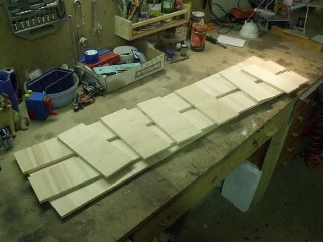
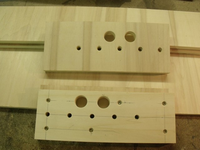
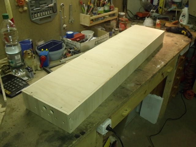
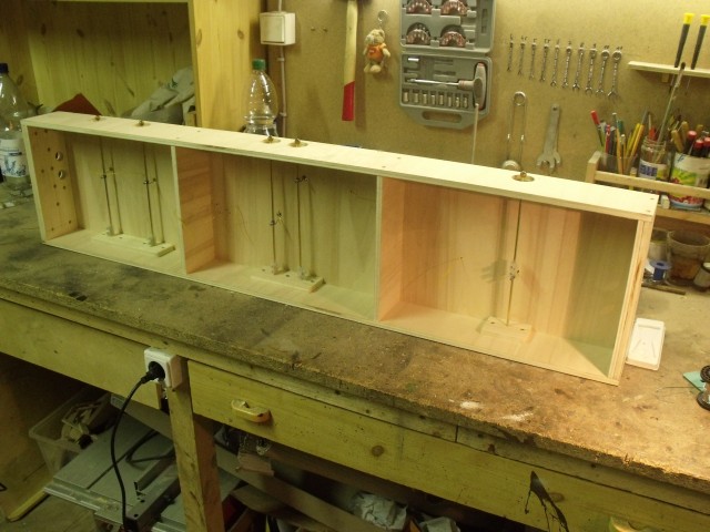
First I build two sandwiches from 25x10cm plywood and the thinner 25x9cm pieces to make the end sills. The 8mm plywood pieces are screwed and glued to the lower inside of the larger pieces to form an edge on top where the base plate will rest. The bore pattern will match the FREMO-americaN standards for industry modules. I just added two 22mm bores for the connecting wires.
With two cross sills
and two side sills, the module box was screwed together and the base plate was set
between the sills. All was glued and screwed in place.
This box is very strong, was easily built and is very light in fact of the poplar plywood.
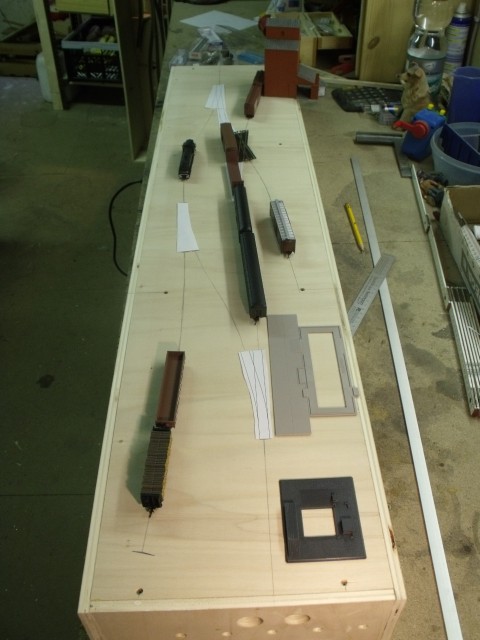
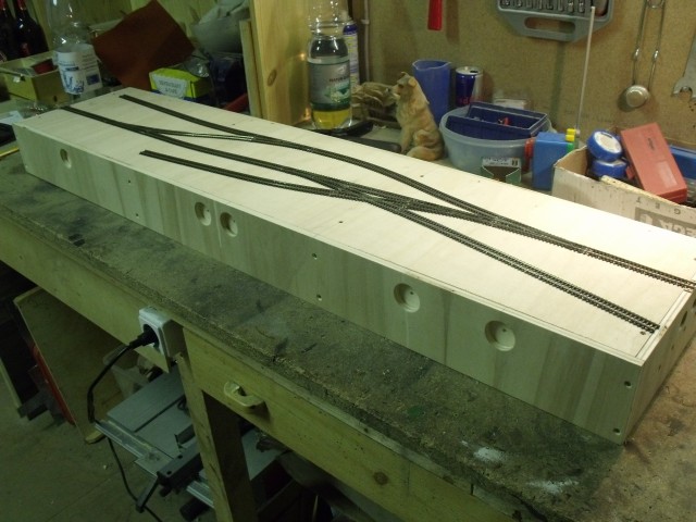
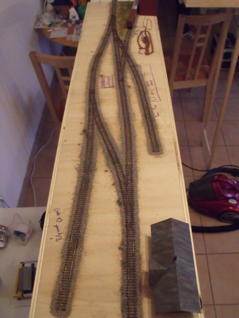
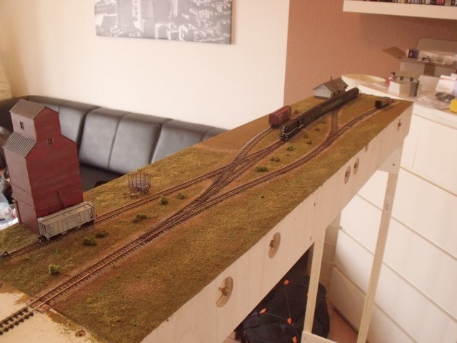
Next I had to layout the final track plan. It turns out very well and much better than shown in the sketch above. I had to change some angles and tracks to get all stuff in place. This picture shows the track plan with main structures (or fundaments).
It turns out, that the useable length of the spurs is much higher than shown in the sketch. I set some trains to the layout to get a feeling for the general impression.
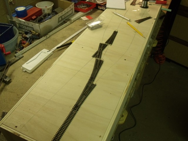
So next I had to install the tracks. I choose Peco c55 tracks. I know that Atlas tracks may be more prototypical, but I had all the Peceo stuff at home. The geometry of the turnouts is also different to the Atlas turnouts, so I would need more space to lay this track plan with #7 or #5 turnouts. So I decided to use what I had at hand.
I started from the entry near the grain elevator while
3 turnouts and the crossing have to be installed in one setup. To connect the turnouts
with the switch mechanism, I drilled holes under the turnouts before I put them in
place.
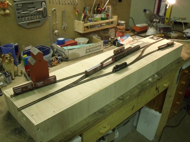
After two hours, the tracks are laid completely, except for the end pieces on the module joints.
Once the switch mechanisms and wiring is done, the first
test runs can be made at Topton.
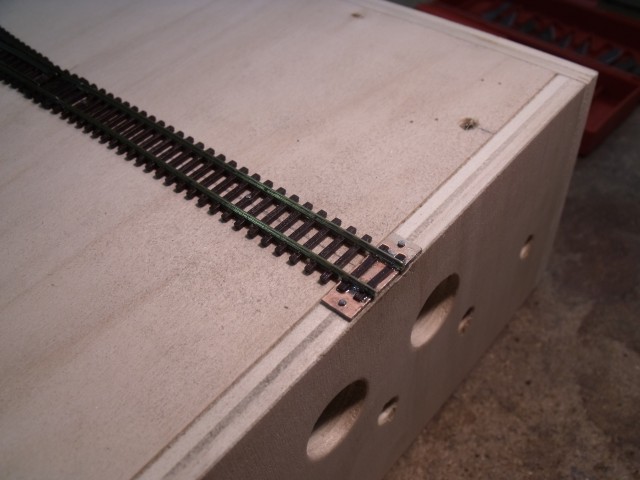
At the module joints, I glued PC-board to the module, fixed with small nails. I soldered the rail ends on top at the right position. The Peco rails have an invisible section inside the ties so it was possible to cut the top half of some spare ties and glue them on top of the PC-board. So the PC board will be invisible when the track is covered with ballast.
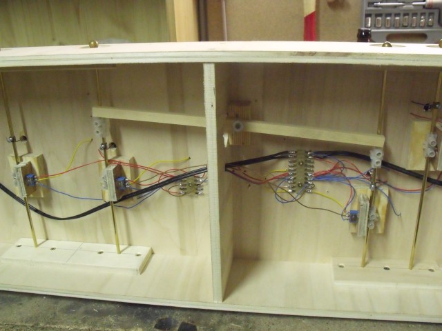
To place the turnout mechanisms, I set 5 35mm bores to the side sills. To operate the module from front and back, I made this on both sides. I set a 10mm plywood behind the holes with a 4,4mm center bore to form small pockets.
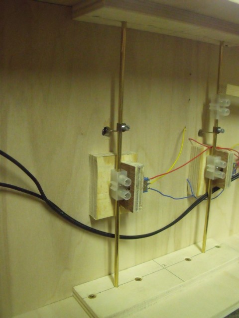
I use a very simple type of switch mechanisms, made from 4mm brass rod and standard switches. First I cut 5 pieces of the brass rod and cut an M4-thread on each end to place ball nuts as handles. During installation, I thread cable clamps to the brass road. One is used to couple the switch and one without plastic (just the brass clamp inside) is used for the connecting wire to the through bar.
Here you can a completed turnour mechanism. The cable clamp is operating the switch and will supply the frog with the currect power. The switch will also hold the turnout in the end position.
For the crossing, I had to install a special lever. If one of the turnouts leading to the crossing is set to curved position, the second have to be in staight. otherwise you'll get a ... The lever will push the first turnout back to straight position, if the second turnout is switched to the branch.
Before I start with the landscape, I weathered the tracks with brown colors out of the airbrush and a drybrush with light grey. I placed some clearence points by painting some ties in yellow. It's a little detail that I often missed on model railroad layouts.
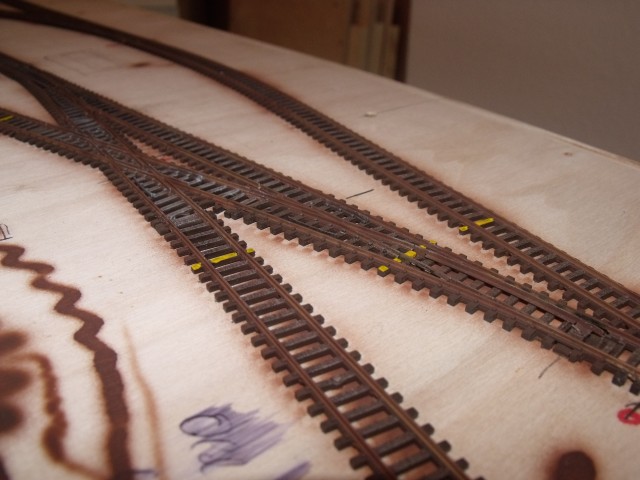
I used fine grey Woodland ballast to ballast the rails. The ballast was glued down in the common way with thinned white glue and I strew some very fine green turf into wet ballast to represent weeds.
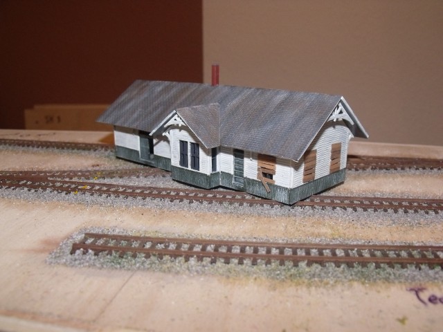
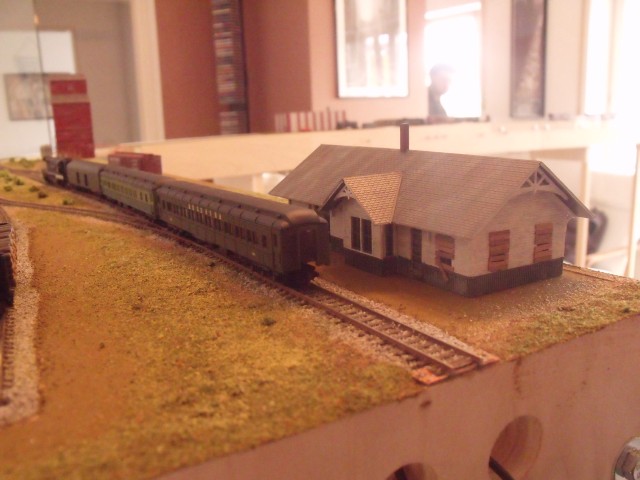
While the glue had to dry, I started with the buildings. The depot was build from a Walthers kit named "Clarksville station" I modified one door of the freight section to an half open version, and painted all parts in a worn out look. I also closed the passenger waiting room by adding boards to the windows.
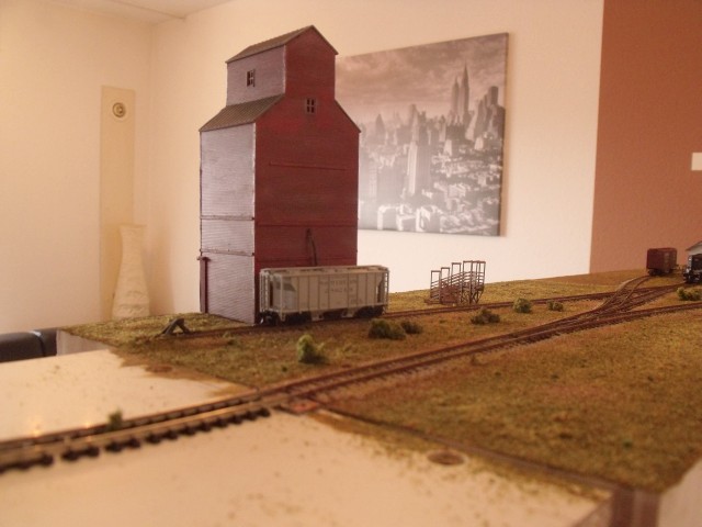
The grain elevator was also build from a Walthers models. I got a build up model at eBay, disassembled the whole elevator and rebuild it to a half relief building, sitting on the edge of the module. The elevator was also repainted and weathered.
You can also see a cattle loading ramp, build from a GC-Laser kit beside the elevator.
Now it was time to add the basic ground stuff. I made a mixture of some Woodland fine turfs to cover the landscape with grass and ground vegetation. I also strew sand into the wet glue along the ballast of the rails and on some other areas. I used a mixture of water and white glue for this.
The depot was placed on the right end of the module at the tail track of the station. I've to add the platform, places and asphalt areas later. You can see the basic ground color at this areas, that I used as a priming.
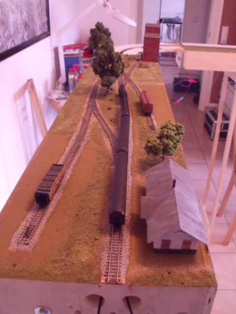
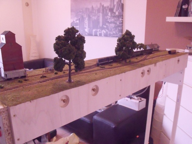
At last some photos of the roughly build module. I placed some trees to get the right impressions of this module and I'm very lucks with it. It turns out much bigger in view, as it is in real. That's what I think.
Now it's time to do all the little thinks and get the whole module detailed with bushes, grasses, people, cars, woods, ... ....