![]()
The brake rigging (part 1)
Another important part of each locomotive are the brakes. I modeled the whole brake rigging in working condition and will try to operate them with steam like the prototype.
![]()
|
|
The brake rigging (part 1) Another important part of each locomotive are the brakes. I modeled the whole brake rigging in working condition and will try to operate them with steam like the prototype. |
|
|
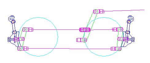
The brake rigging was constructed in AutoCad to check the functionality. I also drawn some parts like links and brake shoes and gave them to a laser cutter. |
|
|
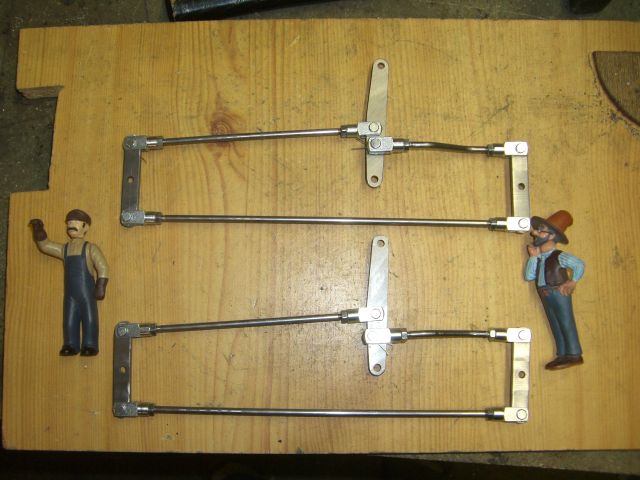
From flat bar, I cut the brake levers and connected them with 4mm rods. As soon as the laser parts are here, I'll continue the work on the brake bars and shoes. |
|
|
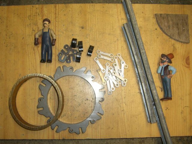
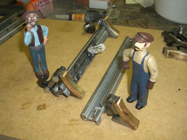
Here are the parts for the brake beams and shoes. I used a laser cut ring with 8 shoes. The break beams are made from rails. |
|
|
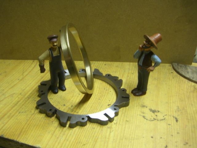
At first, I added a brass ring to the brake shoes as lining and soldered them into the brake shoe ring. |
|
|
In a section of rail, I milled groves to match with the brake shoes and soldered them into place. In the middle, I mounted the head for the brake rigging with screws. |
|
|
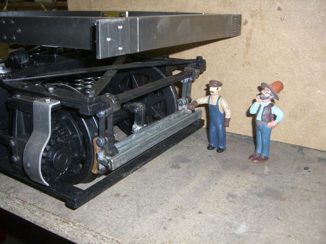
Here the brake beam is mounted to the truck with brake hangers and brake rigging in place. |
|
|
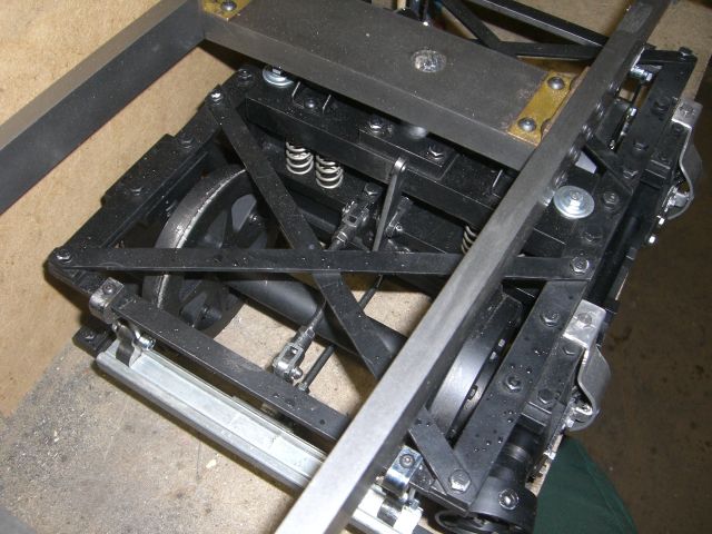
A top view shows the brake rigging in side the front truck and the rear brake beam of the same. Note the main lever in front of the pivot point. By pulling on this lever, the brake will be applied and stop the loco. |
|