![]()
The drive shaft (part 1)
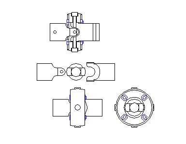
The drive shaft uses universal and slip joints to bring the power from the steam engine to the trucks. On each wheel set, the power is submitted by bevel gears from the drive shaft to the wheel.
![]()
|
|
The drive shaft (part 1) The drive shaft uses universal and slip joints to bring the power from the steam engine to the trucks. On each wheel set, the power is submitted by bevel gears from the drive shaft to the wheel. |
|
|
I'll try to build the universal joints to a prototypical look. I saw a lot of model Shays with simple standard joints and I think a real good model should be built perfect in all points. |
|
|
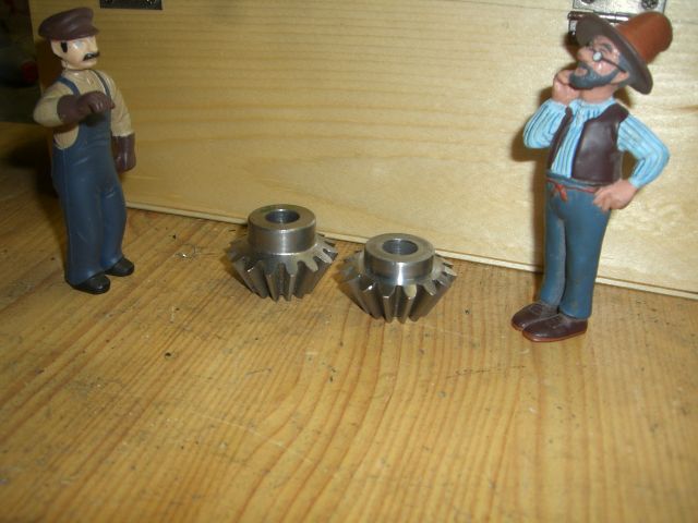
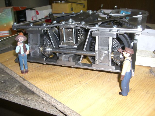
But first, I added the truck drive shafts. I reshaped the bevel pinions on the lathe and bored holes for a set screw and a bolt to fix the gears on the line shaft. |
|
|
I used some brass washer between the pedestals and the gears to hold them in place. |
|
|
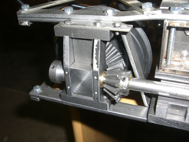
Here's a close up of one of the gears. |
|
|
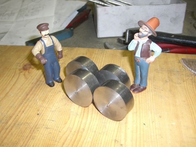
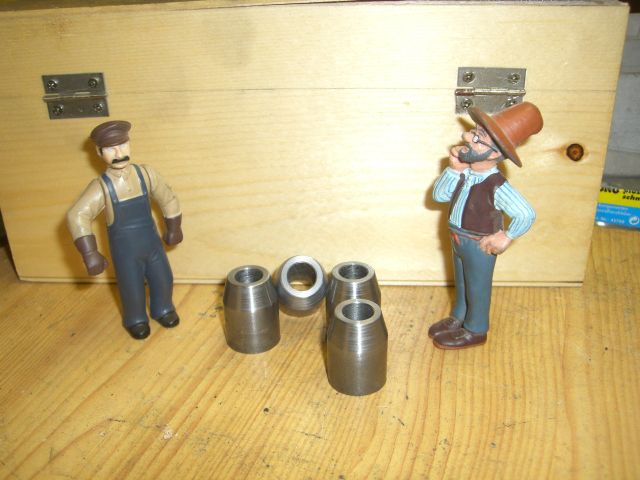
Next I start work on the universal joints. I cut 4 cookies with 40mm diameter and 15mm thick ... |
|
|
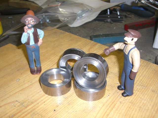
... and bored them to 20.5mm inner diameter and also turned a small recess on each side. |
|
|
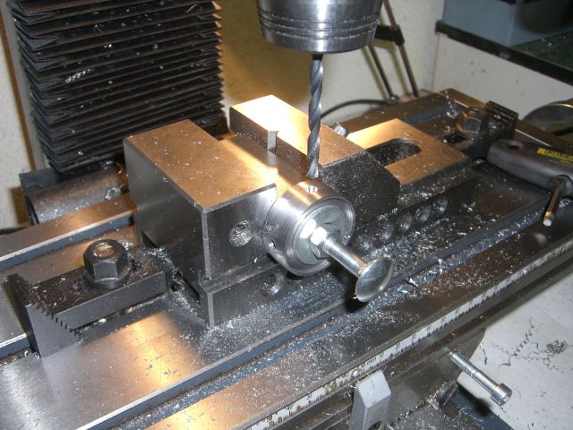
From a 25x25mm square bar, I machined a support to hold the rings on the mill to bore the pin holes. By using a square bar, the hole assemble could be rotated by 90° steps to drill all holes in perfect alignment. |
|
|
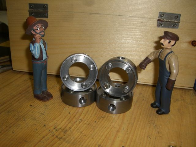
Finally, I slightly rounded the surface and added nut & bolts to the face plates. They are just fakes on my universals. |
|
|
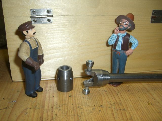
From 20mm steel rod, I cut 4 pieces, bored them with 10mm to match the drive shaft and tapered one end by 15°. |
|
|
Again, I used a square bar to hold the coupling horns during machining them on the mill. First I drilled the holes and shaped the heads with the mill. I use screws for the bolts. |
|
|
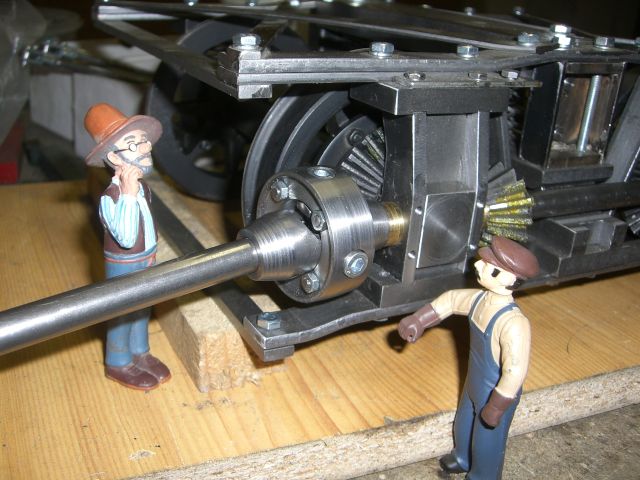
Here I test fitted one of the universal joints to the front truck. The coupling horn on the slip joint will be another design in future. There's a small clip on Youtube of the universal joints driven with an drilling machine. |
|